
ATS & Main-Tie-Main
Transfer logic, operating sequences and interlocking.
Control, monitoring and interlocking engineered around your power system.
From agreed control philosophy to documented logic and interfaces.
Transfer logic, operating sequences and interlocking.
Monitoring, alarm handling and electrical system interfaces.
Control strategies linked to network operating scenarios.
Recover existing logic and engineer the replacement.
Implementation and site support follow the agreed scope.
A standard two-source transfer is usually handled by a dedicated controller — Deep Sea, Socomec or ABB TruONE — and often needs nothing more. We work on the schemes those controllers are not designed for: multi-source, multi-tie arrangements with priority logic, synchronism check and pre-transfer load shedding, where the consultant specification mandates a programmable controller communicating to SCADA or BMS.
Transfer schemes are engineered to IEC 60947-6-1 for transfer switching equipment and IEC 61131-3 for control logic, with synchronism check following the applicable IEEE C37 practice and the project's transfer timing and interlocking specification.
The same team calculates your fault levels and sets your relays. Automation logic that has to interact with protection is written by people who understand both sides of it.
Logic is verified in simulation against the agreed operating and failure scenarios and demonstrated in a virtual FAT before hardware is assembled. Panel and site tests then complete the verification.
Automatic Transfer Switch schemes decide what happens to your critical loads in the seconds after a supply is lost. We design them three ways — as hardwired logic, configured inside numerical relays, or on dedicated PLC control — and recommend the one that matches your availability requirement and maintenance capability, not the one that suits a particular supplier.
Design references IEC 61850 where a station bus is used, IEC 60255 for relay functions, and the IEEE C37 series for transfer scheme practice.
When an islanded plant loses its utility tie or a gas turbine trips, non-essential load may have to be shed within tens of milliseconds to keep the captive grid stable. Which feeders are shed, in what order, and on what trigger is a power system question before it is a programming one — which is why it is engineered together with the power system studies.
Contingency cases are derived from load flow and stability studies prepared to IEEE 399 and IEEE 1110, with control logic to IEC 61131-3 and redundant Ethernet to IEC 62439 (MRP).
The same team calculates your fault levels and sets your relays. Automation logic that has to interact with protection is written by people who understand both sides of it.
Logic is verified in simulation against the agreed operating and failure scenarios and demonstrated in a virtual FAT before hardware is assembled. Panel and site tests then complete the verification.
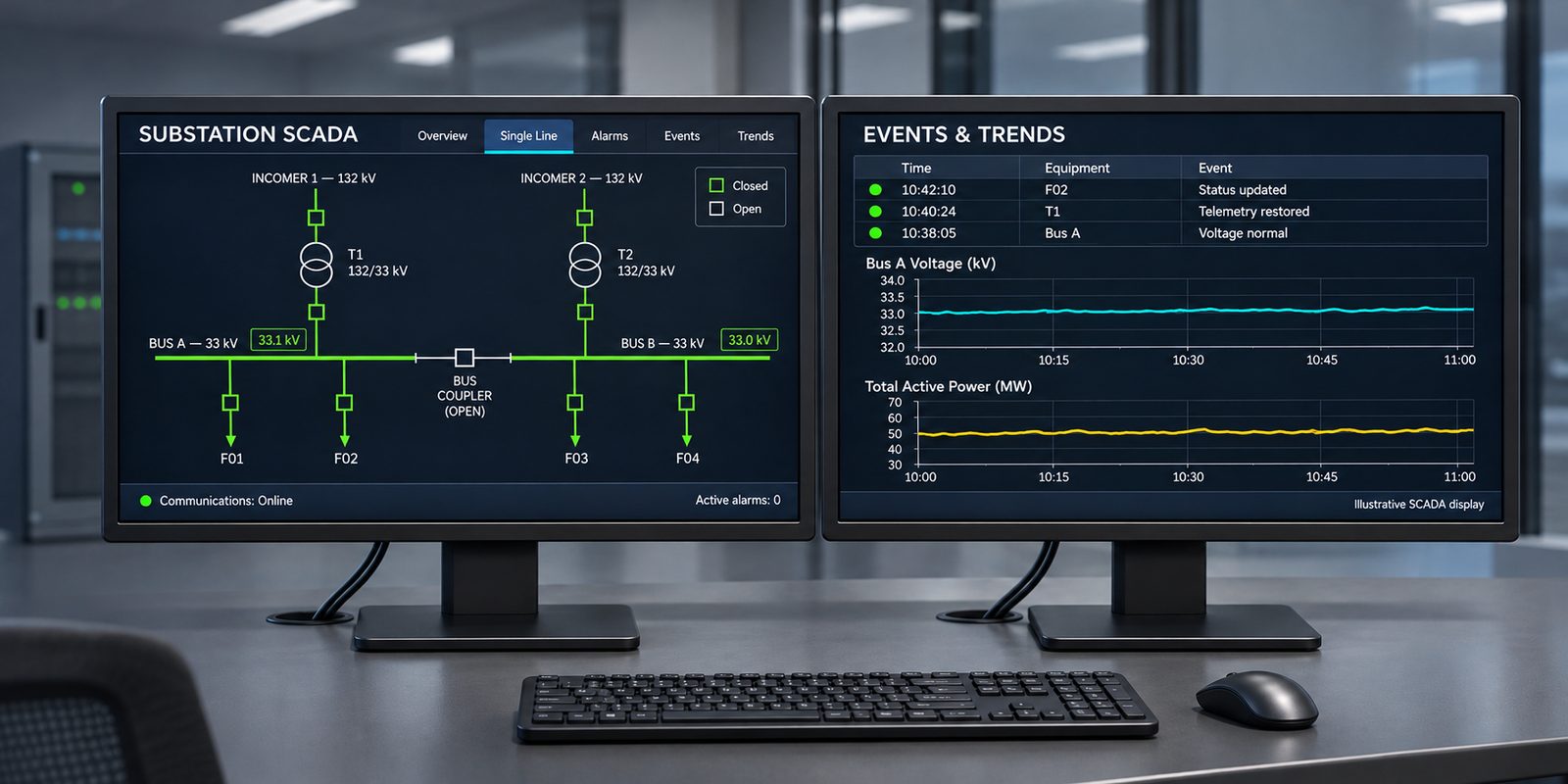
An Electrical Control and Monitoring System pulls your numerical relays, power meters and transformer controllers into one workstation and presents them as a live single-line diagram. The engineering difficulty is rarely the graphics — it is knowing what the relay data objects actually mean and which alarms matter.
Communications are engineered to IEC 61850 for substation data and the relevant Modbus and Profinet specifications, with network segmentation reviewed against IEC 62443 principles for industrial control system security.
The same team calculates your fault levels and sets your relays. Automation logic that has to interact with protection is written by people who understand both sides of it.
Logic is verified in simulation against the agreed operating and failure scenarios and demonstrated in a virtual FAT before hardware is assembled. Panel and site tests then complete the verification.
Legacy S7-200, S7-300, S7-400 and Moeller or Telemecanique controllers reach a point where spares dry up and the original programmer is long gone. The risk in these projects is rarely the conversion itself — it is the undocumented logic nobody can explain, which is why the audit comes before anything is rewritten.
Converted logic is structured to IEC 61131-3, with network migration to the applicable Profinet and Profibus specifications and schematics to IEC 81346 reference designation practice.
The same team calculates your fault levels and sets your relays. Automation logic that has to interact with protection is written by people who understand both sides of it.
Logic is verified in simulation against the agreed operating and failure scenarios and demonstrated in a virtual FAT before hardware is assembled. Panel and site tests then complete the verification.