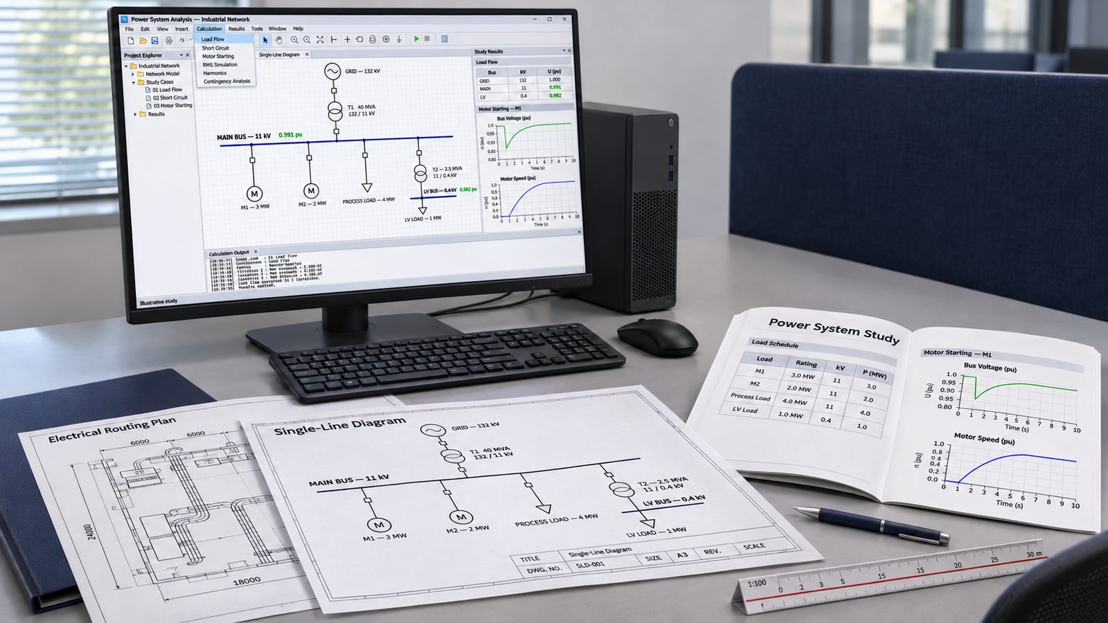
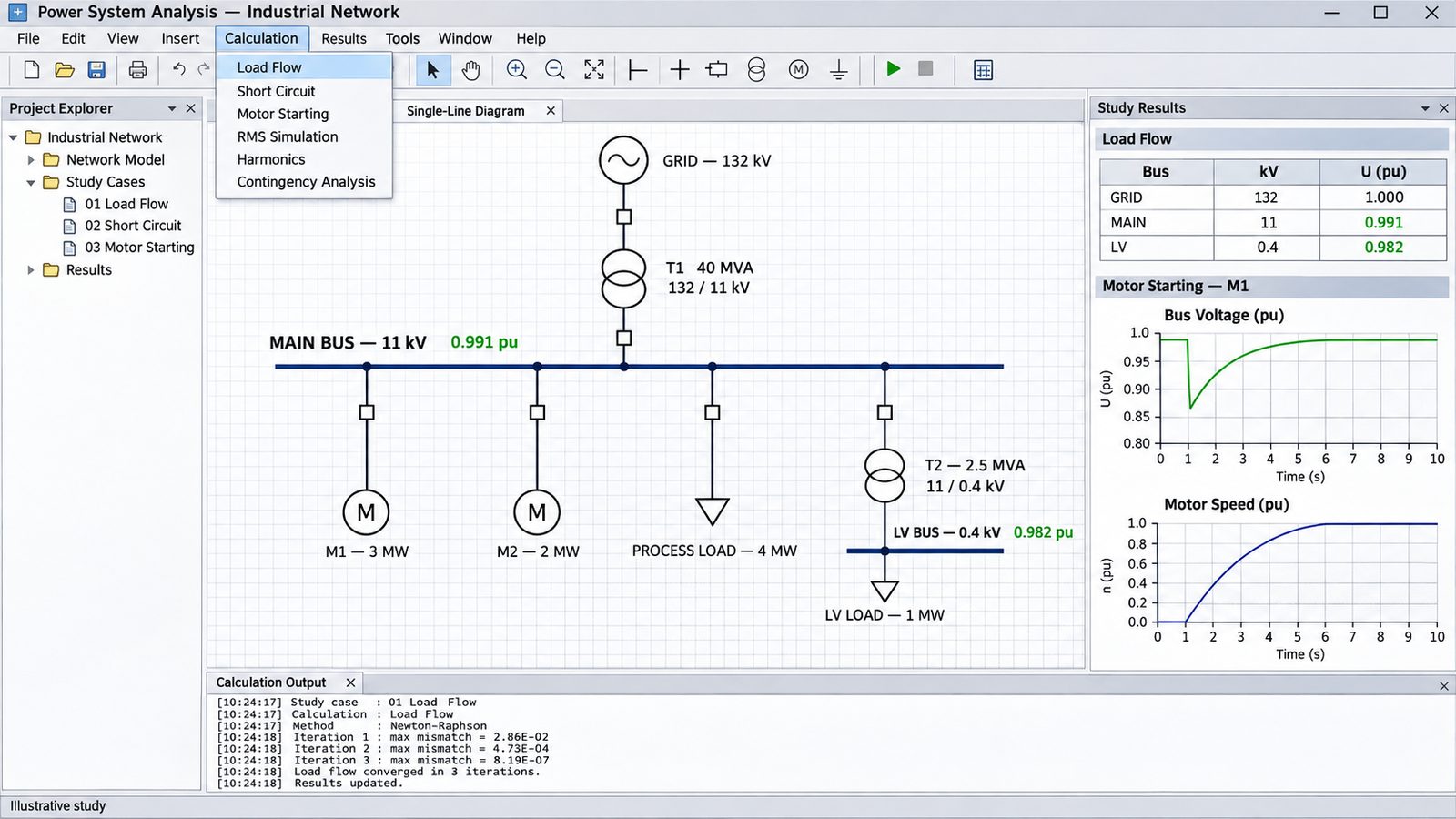
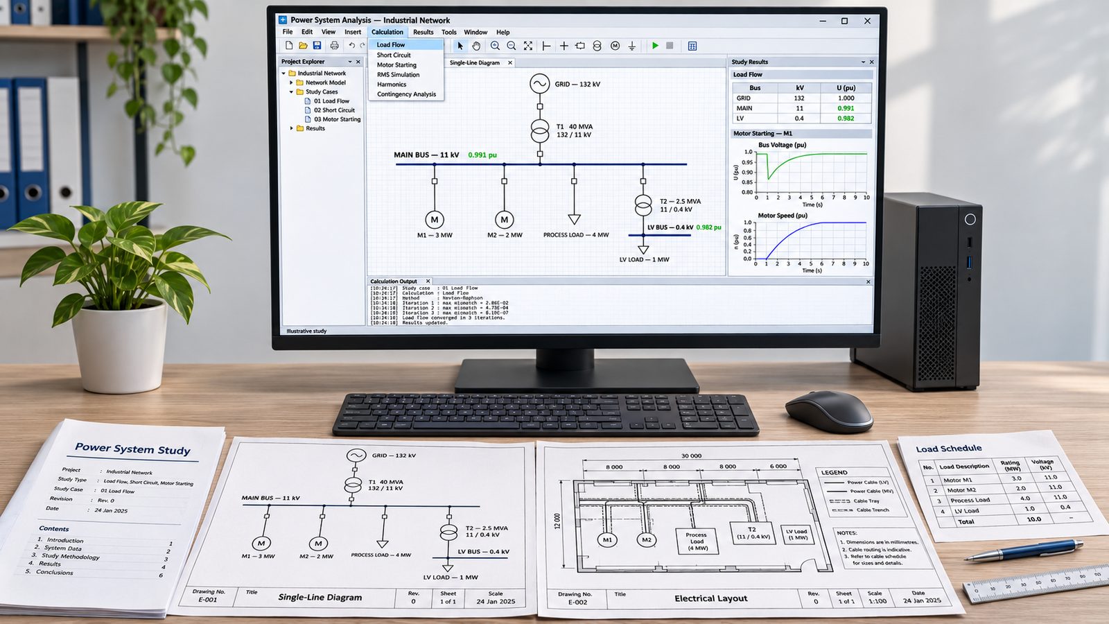
Load Flow Analysis
Load flow analysis tells you whether your network holds up under the conditions it will actually be operated in — not just the design case. It underpins equipment sizing, voltage compliance and every study that follows.
What this covers
- Voltage profile — bus voltages across normal, peak, minimum and contingency operating cases.
- Equipment loading — transformer, cable and busbar loading against continuous and emergency ratings.
- Reactive power and power factor — reactive flow, compensation requirements and capacitor bank sizing.
- Transformer tap settings — fixed and on-load tap changer ranges to hold voltage within limits.
- Contingency cases — network behaviour with a transformer or feeder out of service.
- Losses — where real power is being lost and what it costs over an operating year.
Standards and references
Studies are prepared with reference to IEEE 399 for industrial power system analysis and IEC 60038 for standard voltage limits, alongside the applicable grid code.
Short Circuit Analysis
Short circuit analysis establishes how much current flows when something fails, which determines whether your switchgear can interrupt it and whether your protection can detect it. Both minimum and maximum fault levels matter, for different reasons.
What this covers
- Maximum fault levels — three-phase and phase-to-phase currents used to verify equipment withstand and breaking capacity.
- Minimum fault levels — the cases that determine whether protection will reliably pick up a genuine fault.
- Earth fault currents — single phase to earth and double phase to earth, including the effect of the earthing arrangement.
- Equipment rating verification — breaking, making and short-time withstand ratings against calculated duties.
- Motor and generator contribution — the sub-transient contribution from rotating plant that is often underestimated.
- DC component and asymmetry — peak and asymmetrical duties for breaker rating checks.
Standards and references
Calculations follow IEC 60909 or ANSI/IEEE C37.010 depending on the project basis, with equipment duties assessed against IEC 62271 and the relevant IEEE C37 series ratings.
Arc Flash Studies
Arc flash analysis quantifies the thermal hazard at each point where someone may work on or near energised equipment, so that PPE decisions rest on calculated incident energy rather than assumption. Because incident energy depends directly on clearing time, the study is inseparable from your protection settings.
What this covers
- Incident energy calculation — at each working position, based on actual fault level and protection clearing time.
- Arc flash boundary — the distance at which incident energy falls to the second-degree burn threshold.
- PPE category assignment — matching protective equipment to calculated energy at each location.
- Label content — the information required on equipment warning labels.
- Mitigation options — maintenance switching modes, zone-selective interlocking, arc flash relays and setting changes that reduce clearing time.
- High-energy locations — identifying points where energy cannot be reduced and access must be controlled instead.
Standards and references
Analysis is carried out to IEEE 1584 for incident energy calculation and NFPA 70E for boundaries, PPE and safe work practice, with fault data derived to IEC 60909 or ANSI/IEEE C37.010.
Motor Starting Analysis
Large motors draw several times full-load current on start, and the resulting voltage dip can stall other motors, drop out contactors and trip protection elsewhere on the network. Motor starting analysis establishes whether a given motor can be started on a given supply, and what starting method is needed if it cannot.
What this covers
- Voltage dip — magnitude and duration at the motor terminals and across the wider network.
- Starting current profile — inrush and run-up current against time.
- Torque analysis — motor torque against load torque throughout run-up, assessing whether the motor accelerates under the studied supply conditions.
- Acceleration time — checked against the motor thermal withstand and locked-rotor limits.
- Starting method comparison — direct on line, soft starter, star-delta, autotransformer and variable speed drive.
- Effect on other loads — contactor drop-out, undervoltage tripping and stalling risk on running motors.
- Generator-supplied cases — starting behaviour where the source is a generator rather than a stiff utility supply.
Standards and references
Studies reference IEEE 399 for analysis method and IEC 60034 for machine characteristics, with acceptable voltage dip assessed against the project specification and IEC 60038.
Power System Stability Analysis
Stability analysis answers what happens in the seconds after a disturbance: whether generators stay in step, whether motors reaccelerate, and whether the network recovers or collapses. It matters most where you have local generation, large motor loads, or an islanding requirement.
What this covers
- Transient stability — generator rotor angle and machine synchronism following faults and switching events.
- Critical clearing time — the longest fault duration for which the studied system remains stable, which feeds directly back into protection settings.
- Voltage stability — recovery behaviour and the risk of voltage collapse under heavy loading.
- Motor reacceleration — whether motor loads recover after a fault or stall and must be shed.
- Islanding and load shedding — behaviour on separation from the grid, and the load shedding needed to keep the studied cases stable.
- Frequency response — governor and generator response to load and generation imbalance.
Standards and references
Analysis references IEEE 399 and IEEE 1110 for machine modelling, with acceptance criteria taken from the project specification and applicable grid code.
Earthing System Design
An earthing system has to do two things at once: keep step and touch voltages within safe limits during a fault, and give fault current a reliable path so protection operates. Both depend on soil resistivity, which is why the design starts with measured data rather than assumed values.
What this covers
- Soil resistivity interpretation — deriving a layered soil model from measured field data.
- Earth grid design — conductor layout, spacing, depth and rod arrangement.
- Step and touch voltage — calculated against tolerable limits for the fault duration and surface layer used.
- Ground potential rise — magnitude and the transferred potential implications for incoming services and communications.
- Conductor sizing — thermal sizing of earth conductors for the fault duty and duration.
- Earthing arrangement — solid, resistance or resonant earthing and the fault current each produces.
- Lightning and surge — coordination with lightning protection and surge arrester earthing.
Standards and references
Design is carried out to IEEE 80 for substation earthing and IEC 61936-1 for AC installations above 1 kV, with soil measurement to IEEE 81 and conductor sizing to IEC 60949.
Power System Design
Power system design sets the shape of the network — how many sources, how they are configured, what each item of plant has to withstand, and how the system behaves when part of it is lost. Every study we run and every relay we set traces back to decisions made here, which is why we prefer to be involved before the single-line is frozen.
What this covers
- Network topology — radial, ring and dual-source arrangements, and the availability each actually delivers.
- Substation configuration — single busbar, sectionalised, double busbar and main-and-transfer, assessed against operational and maintenance requirements.
- Voltage selection and transformation — voltage levels, transformer sizing, impedance and tap range.
- Equipment rating — switchgear, cable and busbar duties verified against calculated fault levels and continuous and emergency loading.
- Earthing arrangement — solid, resistance or resonant earthing, and the fault current and protection consequences of each.
- System earthing design — grid layout, step and touch voltage, and ground potential rise.
- Protection philosophy interface — checking that the design can be protected selectively before it is built.
Standards and references
Design references IEC 61936-1 for AC installations above 1 kV, IEC 60909 or ANSI/IEEE C37.010 for fault levels, IEEE 80 for earthing and IEC 60038 for standard voltages, together with the applicable grid code.
We hold no distributor agreements, so the recommendation reflects what suits your network rather than what suits a supplier.